This section will cover the details of how to remove, refit and replace all serviceable parts of the portable lift. Ensure to read and understand each step thoroughly before removing any component from the portable lift.
Ideally, the portable lift should be removed from the track and placed on a work bench before any dismantling. However servicing can be done with the portable lift remaining within the track system. (Depending on the service required).
Unless stated otherwise, all images refer to a Mackworth CPP with a standard trolley assembly (Track Type 1). Where necessary, additional images for alternative track and portable lift types have been included.
Before carrying out any dismantling of the portable lift, the power should be turned off using the red pull cord.
8.1 Side Covers
This section will cover the details of how to remove, refit and replace the portable lift side covers.
Removal
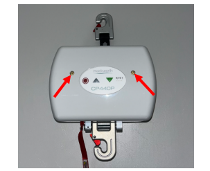
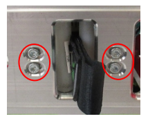
1. Use a slotted screwdriver to remove the two brass screws from the rear cover of the portable lift.
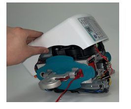
2. Gently remove the cover from the portable lift.
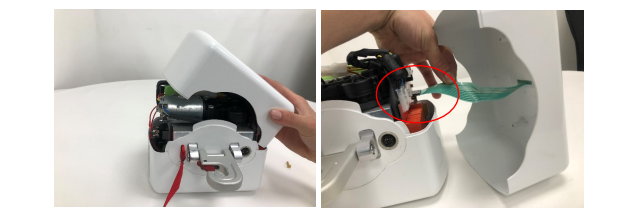
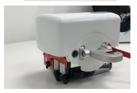
3. Rotate the portable lift 180° and gently rest the portable lift on the lift motor.
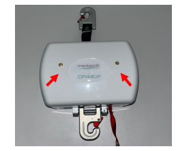
4. Using a slotted screwdriver, remove the two brass screws from the front cover.
5. Gently remove the cover from the Portable lift.
Refitting / Replacement
Refitting is a reversal of the removal process noting the following points:
• Make sure the profile edges of the covers align with the bottom cover.
8.2 Top/Bottom Covers
8.2.1 Top Cover
This section will cover the details of how to remove, refit and replace the portable lift top cover.
Removal
1. Remove the side covers from the portable lift. (Refer to section 8.1)
2. Remove the PCB from the portable lift. (Refer to section 8.4)
3. Remove the top QRS Hook from the chassis. (Refer to section 8.13)
4. Remove the QRS Hook from the lift tape. (Refer to section 8.13)
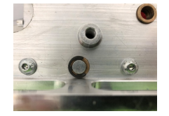
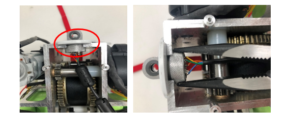
5. Using long nose pliers, remove the bung that secures the cover to the chassis by pressing the retaining clips inwards.
6. Pull the top cover away from the chassis and feed the lift tape through the slot to remove it.
Refitting / Replacement
Refitting is a reversal of the removal process noting the following points:
• Make sure the cover slot is fed through the lift tape in the correct direction.
• Make sure to align the cover with the bung hole.
• Attach the bung by pressing the bung into the hole.
8.2.2 Bottom Cover
This section will cover the details of how to remove, refit and replace the portable lifts bottom cover.
Removal
1. Remove the side covers from the portable lift. (Refer to section 8.1)
2. Remove the PCB from the portable lift. (Refer to section 8.4)
3. Remove the QRS Hook from the chassis. (Refer to section 8.13)
4. Remove the handset cable port from the portable lift. (Refer to section 8.11)
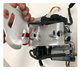
5. Pull the top cover away from the chassis to remove.
Refitting / Replacement
Refitting is a reversal of the removal process noting the following points:
• Ensure the red pull cord is pulled through its designated slot.
• Ensure that the handset port fits into its designated slot.
• Ensure that the bottom cover is flush up against the bottom of the chassis
8.3 Batteries
This section will cover the details of how to remove, refit and replace the batteries.
Removal
1. Remove the side covers from the portable lift. (Refer to section 8.1)
2. Disconnect the battery power leads from the PCB.
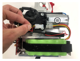
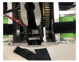
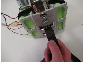
3. Release the Velcro straps to give access to the batteries.
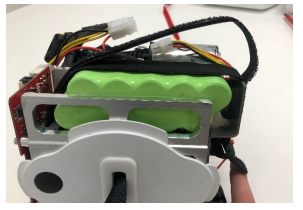
4. Remove the battery from its position
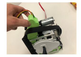
5. Repeat step 2 to 6 to remove the opposite battery.
Refitting / Replacement
Refitting is a reversal of the removal process noting the following points:
• Ensure to place the batteries back into the brackets in the correct orientation. (the cable should be at the PCB end facing outwards).
• Ensure that the battery A and motor A are on the same face of the chassis. Same applies to battery B and motor B. Battery B does NOT have a suppressor on the cable.
• Ensure the Velcro is reattached correctly.
8.4 PCB
This section will cover the details of how to remove, refit, and replace the PCB.
Removal
1. Remove the side covers from the portable lift. (Refer to section 8.1)
2. Disconnect the power leads from the PCB.
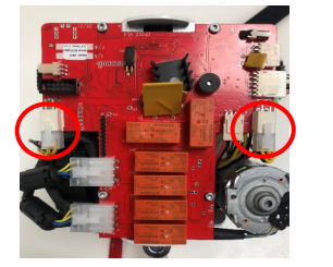
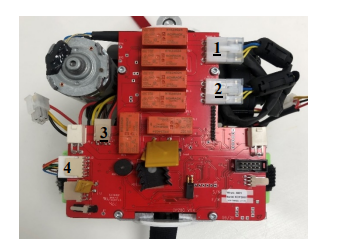
3. Remove the remaining connections from the PCB ports. There is no correct order to disconnect.
• Motor A
• Motor B
• Limit Switch
• Handset Port
4. Using a 2.5mm Allen Key, remove the four M3 screws securing the board to the chassis.
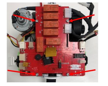
5. The PCB can now be removed from the portable lift.
Refitting / Replacement
Refitting is a reversal of the removal process noting the following points:
• The power lead should always be connected last.
• Make sure to connect each component to the correct port.
• Ensure that the motors are connected to the correct port. The correct motor port is inscribed onto the PCB.
• Make sure to secure the PCB to the chassis before reconnecting the power, do not allow the board to come into contact with the chassis other than its designated mounts.
8.5 Lift Motor
This section will cover the details of how to remove, refit, and replace the Lift Motor.
Removal
1. Remove the side covers from the portable lift. (Refer to section 8.1)
2. Disconnect the power lead from the PCB.
3. Disconnect the motor leads from the PCB. (See section 8.4 for further information)
4. Remove the cable routing of lift motor B from under the PCB. (PCB removal is recommended)
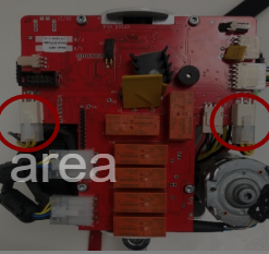
5. Using a 5mm Allen Key, remove the two bolts securing the motor to the chassis.
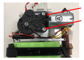
6. Remove the motor from the chassis, be careful not to damage the gear shaft during removal.
7. Repeat step 5 and 6 to remove the opposite motor.
Refitting / Replacement
Refitting is a reversal of the removal process noting the following points:
• Ensure that the motor aligns with the tapped holes on the motor mount.
• Ensure that Motor A and B are attached to the correct face. Use the PCB for reference.
• Ensure to route the Motor B cable under the PCB.
• Ensure that the motor cables are connected to the correct port on the PCB.
8.6 Lift Tape
This section will cover the details of how to remove, refit and replace the Lift Tape.
Removal
1. Remove the side covers from the portable lift. (Refer to section 8.1)
2. Remove the PCB from the portable lift. (Refer to section 8.4)
3. Remove the top QRS hook from the portable lift. (Refer to section 8.13)
4. Remove the top cover from the portable lift. (Refer to section 8.2)
5. Remove the motors from the portable lift. (Refer to section 8.5)
6. Pull the lift tape from the portable lift until it has fully unwound from the hub.
7. Using a small slotted screwdriver, remove the 8mm e-clip from the strap pin. Be careful not to lose the e-clip.
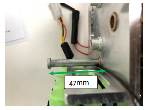
8. Slide the strap pin out of the chassis until 47mm of the pin is visible, this allows lift tape removal without displacing the hub.
9. Gently pull the lift tape through the limit switches to remove from the portable lift.
Refitting / Replacement
Refitting is a reversal of the removal process noting the following points:
When refitting the lift tape, ensure that the stitching fold is opposing the face of the black bung.
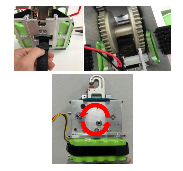
• For easier refitment, open up the loop of the tape as shown, this can make it easier for the strap pin to fit through the tape when inside the hub.
• When sliding the pin back through the chassis, be careful not to catch the lift tape and cause damage to its integrity.
• Inspect the condition of the e-clip, if the clip has been stretched, replace with a new e-clip.
• Once the pin is pushed back through the chassis, ensure to refit the e-clip. This is done using long nose pliers.
• Wind the lift tape around the hub by rotating the hub in an anti-clockwise direction.
• Pull the lift tape while holding the hub to allow the lift tape to stretch and tighten, then continue to wind around the hub.
• Refit the removed components to the portable lift.
8.7 Lift Hub (Spool)
This section will cover the details of how to remove, refit and replace the Lift Tape.
Removal
1. Remove the side covers from the portable lift. (Refer to section 8.1)
2. Remove the PCB from the portable lift. (Refer to section 8.4)
3. Remove the top cover from the portable lift. (Refer to section 8.2)
4. Remove the lift motors from the portable lift. (Refer to section 8.5)
5. Remove the motor shafts from the portable lift. (Refer to section 8.10)
6. Remove the lift tape from the portable lift (Refer to section 8.6)
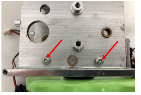
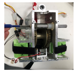
7. Using a 4mm Allen Key, remove the two overspeed screws from the chassis.
8. Remove the strap pin from the chassis, this should already be loose from the lift tape removal. If not, remove the 8mm e-clip.
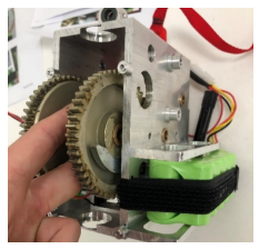
9. Slowly guide the hub out of the chassis. Be careful not to damage the teeth during removal.
Refitting / Replacement
Refitting is a reversal of the removal process noting the following points:
• When refitting the hub, if required, grease the hub using the recommended grease (Morris Grease – K42EP multi-purpose).
• When inserting the hub back into the chassis, make sure the Overspeed cam is facing the same face as the overspeed cam screws.
• Make sure to refit the overspeed cam screws into the chassis.
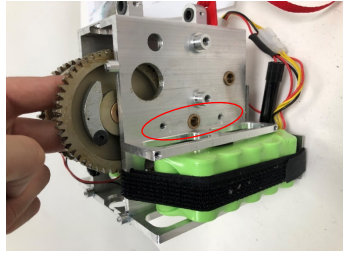
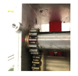
• Test the overspeed cam is working by flicking the cam with an Allen Key through the slot in the chassis. (See image below)
• Refer to the lift tape refitting guide for further details.
8.8 Limit Switches
This section will cover the details of how to remove, refit and replace the Limit Switches.
Removal
1. Remove the side covers from the portable lift. (Refer to section 8.1)
2. Remove the PCB from the portable lift. (Refer to section 8.4)
3. Remove the batteries from the portable lift. (Refer to section 8.3)
4. Remove the handset port from the portable lift. (Refer to section 8.11)
5. Remove the top cover from the portable lift. (Refer to section 8.2)
6. Remove the e-stop assembly from the portable lift. (Refer to section 8.9)
7. Using a 3mm Allen Key, remove the four screws shown to release the limit switch assembly.
8. Once the four screws have been removed, remove the limit switch assembly through the side exit of the chassis. Be careful not to trap/catch the wiring while removing
Refitting / Replacement
Refitting is a reversal of the removal process noting the following points:
• When fixing the individual switches, fix the black and brown wire block to the back face of the portable lift first (e-stop side)
• Route the black and brown wire along the chassis side face underneath motor A.
• Fix the black and red wire block to the front face of the portable lift (PCB side)
• Attach the limit switches to the chassis with the four screws but do not tighten.
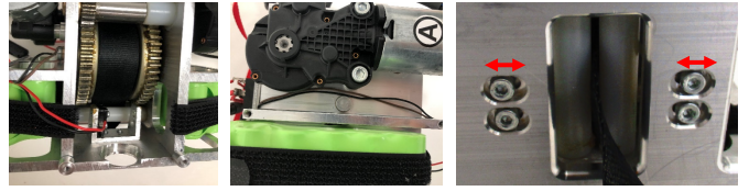
• To set the switches, slide a switch inward until it activates against the roller (the switch will click). Once it has activated, move the switch outward until it is released. (the switch will click again). Once it has been released, tighten the screws to set the limit switch.
• Repeat these steps for the second limit switch.
• Manually test whether the switches are working by pressing the rollers in and out. You should hear the switches clicking when activated and released.
8.9 Toggle Switch and E-Lower Cord
This section will cover the details of how to remove, refit and replace the Toggle Switch assembly.
Removal
1. Remove the side covers from the portable lift. (Refer to section 8.1)
2. Remove the batteries from the portable lift. (Refer to section 8.2)
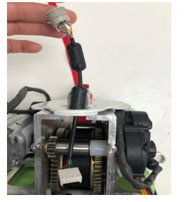
3. Remove the 6 screws which secure the toggle switch assembly to the chassis using a 2mm Allen Key.
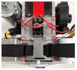
4. Remove the toggle switch assembly from the chassis, and slide the pull cord out of the chassis slit.
Refitting / Replacement
Refitting is a reversal of the removal process noting the following points:
• Ensure to fit the pull cord onto the toggle switch and through the chassis slit.
8.10 Motor Shafts
This section will cover the details of how to remove, refit and replace the motor shafts.
Removal
1. Remove the side covers from the portable lift. (Refer to section 8.1)
2. Remove the PCB form the portable lift. (Refer to section 8.4)
3. Remove the lift motors from the portable lift. (Refer to section 8.5)
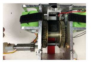
4. Mark a line between the motor shaft tooth and the chassis as shown, these must align to allow the motor to align during refitment.
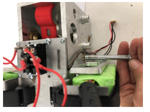
5. Using a parallel pin punch and hammer, lightly tap the motor shaft out from the chassis.
6. Remove the motor shaft from the chassis.
Refitting / Replacement
Refitting is a reversal of the removal process noting the following points:
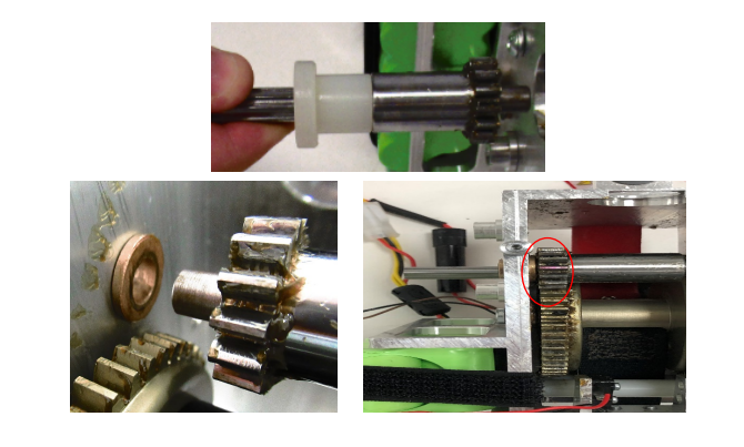
• Ensure that the white spacer is fitted onto the shaft as shown.
• Ensure that the motor shaft fits into the Oilite bush at the other face of the chassis.
• Ensure that the marked line aligns between the shaft and chassis to allow the motors to align correctly.
8.11 Handset Port
This section will cover the details of how to remove, refit and replace the Handset Port.
Removal
1. Remove the side covers from the portable lift. (Refer to section 8.1)
2. Remove the PCB from the portable lift. (Refer to section 8.4)
3. Remove the bottom QRS from the portable lift. (Refer to section 8.13)
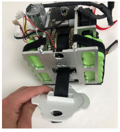
4. Twist and remove the threaded port retainer anticlockwise to release the handset port. (Pliers may be required)
5. Remove the handset port by pulling it through the bottom cover as shown.
Refitting / Replacement
Refitting is a reversal of the removal process noting the following points:
• The handset port will align with a slot in the bottom cover, make sure to fit into this slot before tightening.
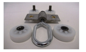
8.12 Trolley Wheels
This section will cover the details of how to remove, refit and replace the trolley wheels, this section covers all wheel variants. The images below refer to track type 1 wheels but the same procedure will apply to all other track types.
Removal
1. Using circlip pliers, remove the circlips from the wheel axel on both wheels.
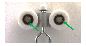
2. Remove the wheels and spacers from the circlip side of the trolley.
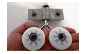
3. Remove the axels with the remaining wheels and spacers from the opposite side of the trolley.
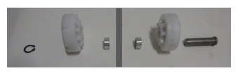
Refitting / Replacement
Refitting is a reversal of the removal process noting the following points:
• When refitting the wheels, see the exploded diagram below for guidance on the assembly order.
• Inspect the condition of the e-clips, if the clips have been stretched, replace with a new e-clip.
8.13 QRS Hooks
8.13.1 Top QRS Hook
This section will cover the details of how to remove, refit and replace the Top QRS Hook.
Removal
1. Using a 2mm Allen Key, loosen the grub screw from the hook until it releases the pin. The grub screw doesn’t need to be fully removed.
2. Slide the pin out from the lift tape to release the QRS Hook.
Refitting / Replacement
Refitting is a reversal of the removal process noting the following points:
• Ensure that the hole in the pin aligns with the grub screw.
• Care must be taken not to damage the lift tape when inserting the pin through the loop.
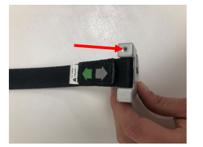
8.13.2 Bottom QRS Hook
This section will cover the details of how to remove, refit and replace the Top QRS Hook.
Removal
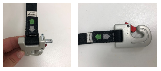
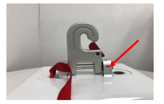
1. Using a 1.5mm Allen Key, remove the two grub screws on either side of the chassis as shown.
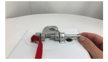
2. Using a 2mm Allen Key, loosen the grub screw on the QRS until it releases its hold on the pin.
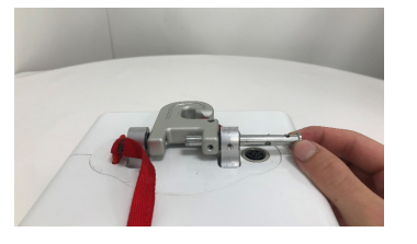
3. Slide the pin out to release the QRS Hook.
Refitting / Replacement
Refitting is a reversal of the removal process noting the following points:
• Ensure that the holes in the pin aligns with the grub screws.