Removal and Replacement
This section will cover the details of how to remove, refit and replace all serviceable parts of the ceiling hoist. Ensure to read and understand each step thoroughly before removing any component from the ceiling hoist.
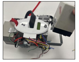
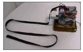
Ideally, the ceiling hoist should be removed from the track and placed on a work bench before any dismantling. But servicing can be done with the ceiling hoist remaining within the track system. (Depending on the service required).
Unless stated otherwise, all images refer to a Transactive Xtra Hoist with a standard wheel assembly (Track Type 1). Where necessary, additional images for alternative track and ceiling hoist types have been included.
Before carrying out any dismantling of the ceiling hoist, the power should be turned off using the red pull cord.
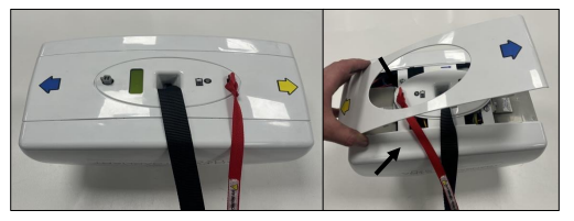
8 . 1 External Covers
This section will cover the details of how to remove, refit and replace the ceiling hoist side covers.
Removal
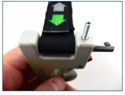
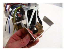
- Place the hoist upside down to access the bottom external cover. Remove the cover by pulling it off from either side.
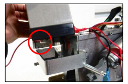
2. Loosen the four screws circled below to release the external covers. The screws do not need to be removed from the chassis.
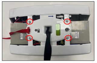
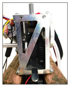
3. Rotate the Hoist and loosen the screws on the top side of the external covers. There are two screws either side of the Top Trolley.
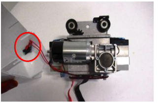
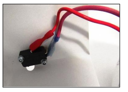
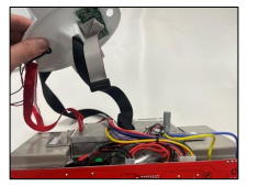
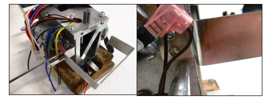
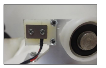
4. Firstly, remove the Motor side cover. Disconnect the motor leads from the switch on the inside of the cover.
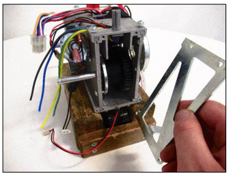
5. Remove the other cover to complete the external covers removal.
Refitting / Replacement
- Refitting is a reversal of the removal process noting the following points:
- Ensure to attach the Motor wires to the correct terminal on the cover switch. See image below.
- Ensure the slots on the top and bottom side of the cover align with pozi screws on the Chassis.
- Refit the Bottom external cover to the Hoist in the correct orientation, the blue and yellow arrows on the external cover and bottom cover should match direction.

8 . 2 QRS Hook
This section will cover the details of how to remove, refit and replace the QRS Hook.
Removal
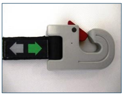
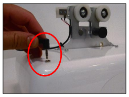
- Using a 2mm Allen key unscrew the grub screw (arrow) until it releases its hold on the Pin.
2. Slide the pin out of the hook to release the Lift Tape.
Refitting / Replacement
- Refitting is a reversal of the removal process noting the following point:
- Make sure the hole in the QRS pin lines up with the grub screw.
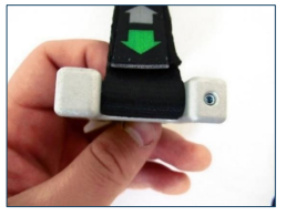
- Ensure the hook is attached to the lift tape in the below orientation
8 . 3 PCB
This section will cover the details of how to remove, refit and replace the PCB.
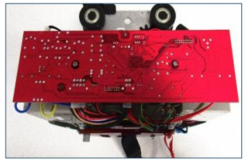
8 . 3 . 1 Powered Traverse PCB
Removal
- Remove the external covers from the ceiling hoist. (Refer to section 8.1)
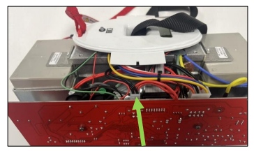
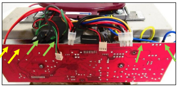
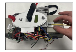
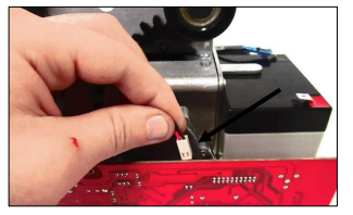
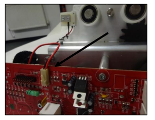
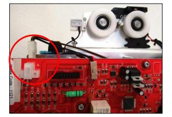
- Remove the power supply cable, by pressing down on the latch and then pull perpendicularly away from the PCB. (Arrowed).
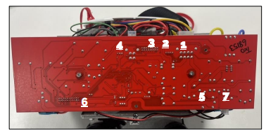
3. Remove the remaining connectors in the numerical order labelled below.
- Toggle switch
- Limit switch
- LCD/Display
- LED
- Traverse Motor
- Charging Beak
- Powered Auxiliary (If applicable)
4. Remove the coloured air tubes (Grey, Green, Yellow and Blue) by gently pulling on the air tubes individually until they release from their individual air switches on the PCB. Powered Auxiliary board will have an additional two tubes (white and black) – these are labelled with a yellow arrow.
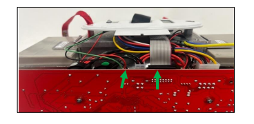
5. Using a 2.5mm Allen key remove the two M3 screws. (arrowed)
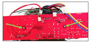
6. Remove the PCB from the Hoist.
Refitting / Replacement
Refitting is a reversal of the removal process noting the following points:
- Make sure the power cable is connected last.
- Air tubes to be fully pushed onto air switches.
- Check for any holes within the airlines.
8 . 4 Batteries
This section will cover the details of how to remove, refit and replace the batteries.
Removal
- Remove external covers of the hoist. (refer to section 8.1).
- Disconnect the power lead from PCB. (See section 8.3 PCB for reference).
- Detach the power cables from the battery terminals.
4. Using a 3mm Allen key, release the two retaining brackets from the chassis to access the batteries.
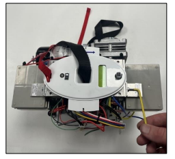
5. Remove both batteries from their brackets.
Refitting / Replacement
6. Refitting is a reversal of the removal process noting the following points:
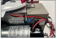
- Make sure the battery terminal is on the outer edge and the terminals are pointing inwards.
- When connecting the main power lead, ensure the positive lead (Red) is fitted to the red terminal, shown in the image above, and the negative lead (Black) is fitted to the black terminal.
- Ensure retaining bracket is fitted in the correct orientation and correct position on the Chassis.
- When connecting the main power lead, ensure the positive lead (Red) is fitted to the red terminal, shown in the image above, and the negative lead (Black) is fitted to the black terminal.
- Ensure retaining bracket is fitted in the correct orientation and correct position on the Chassis.
8 . 5 Bottom Cover
This section will cover the details of how to remove, refit and replace the bottom cover.
Removal
- Remove external covers of the hoist (refer to section 8.1)
- Disconnect the Power Lead from the PCB (Refer to section 8.3)
- Disconnect the LED and LCD Display leads from the PCB.
4. Pull the bottom cover away from the hoist as shown.
Refitting / Replacement
5. Refitting is a reversal of the removal process noting the following point:
• Ensure that the Lift Tape and E-Lower Cord are pulled through their designated slots on the Bottom Cover.
8 . 6 Lift Motor
This section will cover the details of how to remove, refit and replace the lift motor.
Removal
1. Remove external covers of the hoist. (refer to section 8.1).
2. Disconnect the power lead from PCB. (further information refer to section 8.3).
3. Disconnect the Black Motor Lead from the toggle switch connector.
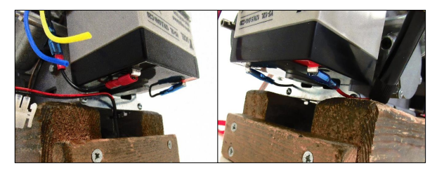
4. Use 5mm Allen key to remove the three bolts. (arrowed).
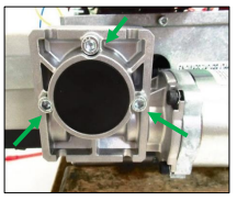
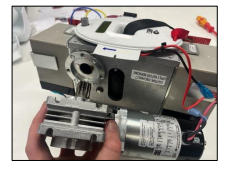
5. Remove the motor, by pulling away from the chassis.
CAUTION! Motor might be hot.
Refitting / Replacement
6. Refitting is a reversal of the removal process.
8 . 7 Battery Bracket
This section will cover the details of how to remove, refit and replace the battery bracket.
Removal
1. Remove external covers off the hoist. (refer to section 8.1).
2. Remove the PCB from the hoist. (refer to section 8.3).
3. Remove the battery from the battery brackets. (refer to section (8.4).
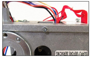
4. Using a 3mm Allen key, remove the two screws securing the bracket to the chassis.
5. Remove the bracket from the hoist, repeat step four to remove the second battery bracket.
Refitting / Replacement
6. Refitting is a reversal of the removal process noting the following point:
• Ensure the bracket is fitted in the correct orientation. Use the image above for reference.
8 . 8 End Plate
This section will cover the details of how to remove, refit and replace the end plate.
Removal
1. Remove external covers off the hoist. (Refer to section 8.1).
2. Remove the PCB from the hoist. (Refer to section 8.3).
3. Remove the Battery from the battery brackets. (Refer to section 8.4).
4. Remove the Battery Brackets. (Refer to section 8.7).
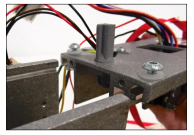
5. Using a 2.5mm Allen Key, remove the three screws securing the End Plate to the Chassis.
6. Remove the End Plate from the Hoist, repeat step five to remove the second battery bracket.
Refitting / Replacement
7. Refitting is a reversal of the removal process noting the following point:
• Ensure the End Plate is fitted in the correct orientation. Use the images above for reference.
8 . 9 Lift Tape
This section will cover the details of how to remove, refit and replace the lift tape.
Removal
1. Remove external covers from the hoist. (Refer to section 9.1)
2. Remove the PCB from the hoist. (Refer to section 8.3)
3. Remove the battery from the battery brackets. (Refer to section 8.4)
4. Remove the bottom cover from the hoist. (Refer to section 8.5)
5. Remove the lift motor from the hoist. (Refer to section 8.6)
6. Remove the battery bracket from the hoist. (Refer to section 8.7)
7. Remove the end plate from the hoist. (Refer to section 8.8)
8. Pull the lift tape until it has fully unwound from the hub
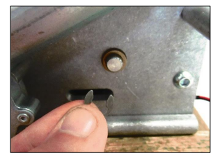
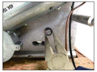
9. Using a small, slotted screwdriver remove the 8mm e-clip from the strap pin.
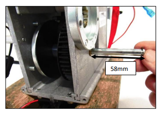
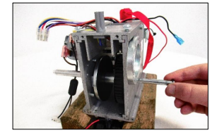
10. Slide the strap pin from the chassis out until 58mm of pin is showing. This will release the lift tape while securing the hub.
11. Gently pull the lift tape through the limit switches to release from the hoist.
Refitting / Replacement
12. Refitting is a reversal of the removal process noting the following point:
• When reinserting the lift tape through the limit switches, make sure that the fold-over lip is facing the red e-lower cord, resulting in the arrow label at the other end also facing the e-lower cord.
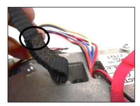
Before inserting the lift tape into the hub, use your thumb to open the loop, this is to help the strap pin slide through once located in the hub.
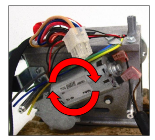
• When winding the lift tape back around the hub make sure to rotate the hub in a clockwise direction while looking at the hoist in the direction shown in the image below.
• Use long noise pliers to reattach the 8mm e-clip to the end of the strap pin.
8 . 10 Hub
This section will cover the details of how to remove, refit and replace the hub.
Removal
1. Remove external covers from the hoist. (Refer to section 8.1)
2. Remove the PCB from the hoist. (Refer to section 8.3)
3. Remove the battery from the battery brackets. (Refer to section 8.4)
4. Remove the bottom cover from the hoist. (Refer to section 8.5)
5. Remove the lift motor from the hoist. (Refer to section 8.6)
6. Remove the battery bracket from the hoist. (Refer to section 8.7)
7. Remove the end plate from the hoist. (Refer to section 8.8)
8. Remove the lift tape from the hoist. (Refer to section 8.9)
9. Remove the strap pin from the chassis.
10. Using a 4mm Allen key, remove the screw shown from the chassis.
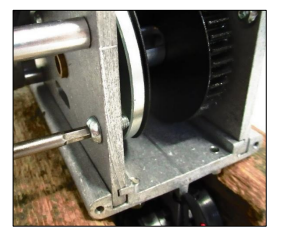
11. Remove the hub from the hoist.
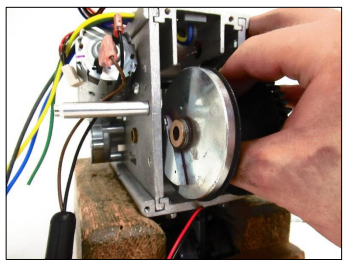
11. Remove the hub from the hoist.
Refitting / Replacement
12. Refitting is a reversal of the removal process noting the following point:
• If replacing hub, grease with Morris Grease – K42EP multi-purpose.
• When inserting the hub back into the chassis make sure the orientation is correct. The OverSpeed Cam must face the PCB side of chassis. See image above.
• Ensure that the two plastic spacers on the hub are either side of the lift tape when inserted.
8 . 11 Bottom Plate
This section will cover the details of how to remove, refit and replace the bottom plate.
Removal
1. Remove external covers from the hoist. (Refer to section 8.1)
2. Remove the PCB from the hoist. (Refer to section 8.3)
3. Remove the battery from the battery brackets. (Refer to section 8.4)
4. Remove the bottom cover from the hoist. (Refer to section 8.5)
5. Remove the lift motor from the hoist. (Refer to section 8.6)
6. Remove the battery bracket from the hoist. (Refer to section 8.7)
7. Remove the end plate from the hoist. (Refer to section 8.8)
8. Remove the lift tape from the hoist. (Refer to section 8.9)
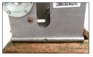
9. Using a 3mm Allen Key, remove the screw retaining the Bottom Plate to the Side Plates, there is one screw either side of the Hoist.
10. The Bottom Plate will slide out of its fixing between the two Side Plates.
Refitting / Replacement
11. Refitting is a reversal of the removal process noting the following point:
• To fit the refit of the Bottom Plate, the Plate must align with the profile of the two Side Plates.
• Ensure the Plate is fitted in the correct orientation. Use the image from Step 10 for reference.
8 . 12 Side Plates
This section will cover the details of how to remove, refit and replace the side plate.
Removal
1. Remove external covers from the hoist. (Refer to section 8.1)
2. Remove the PCB from the hoist. (Refer to section 8.3)
3. Remove the battery from the battery brackets. (Refer to section 8.4)
4. Remove the bottom cover from the hoist. (Refer to section 8.5)
5. Remove the lift motor from the hoist. (Refer to section 8.6)
6. Remove the battery bracket from the hoist. (Refer to section 8.7)
7. Remove the end plate from the hoist. (Refer to section 8.8)
8. Remove the lift tape from the hoist. (Refer to section 8.9)
9. Remove the hub from the hoist. (Refer to section 8.10)
10. Remove the bottom plate from the hoist (Refer to section 8.11)
11. Using a 3mm Allen key, remove the screw retaining the side plates to the top plate, there is one screw either side of the Hoist.
12. The Side Plate will slide out of its fixing with the Top Plate.
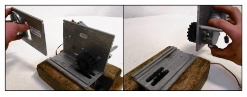
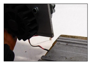
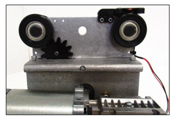
13. (Powered Traverse Only) The Idle Gear can be removed if required by sliding it of the Traverse Shaft.
Refitting / Replacement
14. Refitting is a reversal of the removal process noting the following point:
• To fit the refit the Side Plate, the Plate must align with the profile of the Top Plate.
• Ensure the Plate is fitted in the correct orientation. Use the image from Step 10 for reference.
8 . 13 Top Plate
This section will cover the details of how to remove, refit and replace the top plate.
Removal
1. Remove external covers from the hoist. (Refer to section 8.1)
2. Remove the PCB from the Hoist. (Refer to section 8.3)
3. Remove the battery from the battery brackets. (Refer to section 8.4)
4. Remove the battery bracket from the hoist. (Refer to section 8.7)
5. Remove the end plate from the hoist. (Refer to section 8.8)
6. Step 6 – Using a 3mm Allen Key, remove the screw retaining the Top Plate to the Side Plates, there is one screw either side of the Hoist.
7. The Top Plate will slide out of its fixing with the Side Plates.
Refitting / Replacement
8. Refitting is a reversal of the removal process noting the following point:
• To fit the refit of the Top Plate, the Plate must align with the profile of the Side Plates.
• Ensure the Plate is fitted in the correct orientation. Use the image from Step 6 for reference.
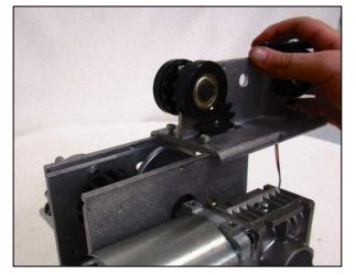
8 . 14 Wheels
This section will cover the details of how to remove, refit and replace all wheel variants use with the ceiling track hoist.
8 . 14 . 1 Wheels (excluding QRT Variants
Within this section it will explain the correct procedure on removing and reinstalling all wheel variants of the hoist (excluding the QRT System Hoist), this section will include track type 1, 2,3,4,5. See Section 1 for guidance on the track type profiles.
The images below refer to the standard wheel (track type 1), but the same procedure will apply to all the wheel variants.
Removal
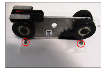
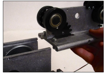
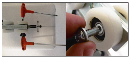
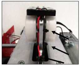
1. Using circlip pliers, remove the circlips from both wheels. (arrowed).
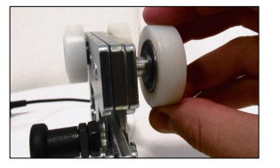
2. Remove the wheel from the hoist as shown – Ensure the spacer and washer is situated within the wheels. Repeat this for the second wheel on the same top plate face.
3. From the opposite face of the Top Plate, remove the Axel along with the other Wheels as shown.
Refitting / Replacement
4. Refitting is a reversal of the removal process noting the following points:
• If replacing with brand new wheels, the below image is an exploded diagram of how the Wheels are fitted together along the axel. The Grey line indicates the Top Plate.
8 . 14 . 2 QRT System Wheels.
Within this section it will explain the correct procedure on removing and reinstalling all-wheel variants of the QRT system hoists, this section will include track type 1, 3, 4 and 5. See Section 1 for guidance on the track type profiles.
Removal
1. Using two 4mm Allen keys, remove the one screw along with its washer from the wheel axel.
2. Remove the wheel and seven washers from the axel.
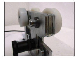
3. Remove the axel along with the second wheel and seven washers from the trolley.
4. Repeat steps 1-3 for the second pair of wheels to complete wheel removal.
Refitting / Replacement
5. Refitting is a reversal of the removal process.
8 . 15 Charging Beak
Within this section it will explain the correct procedure on removing and reinstalling all Charging Dock variants, Including Track Type 1, 2,3,4,5. See section 1 for guidance on the track type profiles.
8 . 15. 1 Charging Beak – Standard (Track Type 1)
Within this section, it will explain the correct procedure on removing and reinstalling the charging beak for servicing procedures or replacement.
Removal
1. Remove external covers off the Hoist. (refer to section 8.1)
2. Disconnect the Charging Beak from the PCB.
3. Re-route the Wire from under the Battery Bracket.
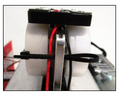
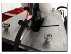
4. Cut the Cable Tie that secure the wire to the Chassis.
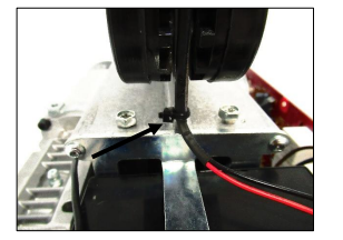
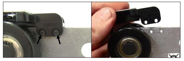
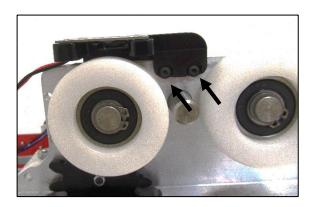
5. Using a 2mm Allen key, remove the M3x12 Screws and M3 nyloc nuts to release the charging beak.
Refitting / Replacement
7. Refitting is a reversal of the removal process noting the following point:
One Cable Tie are requiredl – Re-secure the Wire with cable tie as instructed below:
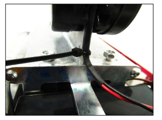
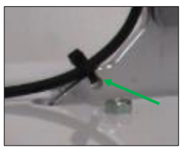
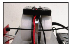
• Insert the Cable Tie through the hole in the Top Plate.
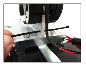
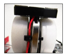
• Close the Cable tie around the Charging Beak wire to retain the wires position. Snip the surplus cable once secured.
8 . 15 . 2 Charging Beak – Track Type 2, 3, 4, 5 and Powered Auxiliary
Within this section, it will explain the correct procedure for removing and reinstalling the Charging Beak for servicing procedures or replacement.
Removal
1. Remove external covers off the hoist. (Refer to section 8.1)
2. Remove the battery from the battery brackets. (Refer to section 8.4)
3. Disconnect the charging beak from the PCB.
4. Reroute the Wire from under the battery bracket.
5. Cut the cable tie that secure the wire to the chassis.
6. Using a pozi screwdriver, remove the screws to release the charging beak.
Refitting / Replacement
8. Refitting is a reversal of the removal process noting the following point:
• One cable tie is required! – Re-secure the Wire with cable tie as instructed below:
• Pass through the cable tie (100×2.5mm) through the hole and tie to secure the wire to the chassis. Snip the surplus cable once secured.
8 . 15. 3 QRT System Charging Beak
Within this section, it will explain the correct procedure for removing and reinstalling the QRT Systems Charging Beak for servicing procedures or replacement.
Removal
1. Disconnect the charging beak from the external cover plug in.
2. Cut the cable tie that secure the wire to the chassis.
3. Using a pozi screwdriver, remove the screws to release the charging beak.
Refitting / Replacement
4. Refitting is a reversal of the removal process noting the following point:
• One cable tie is required! – Re-secure the Wire with cable tie as instructed below:
Pass through the cable tie (100×2.5mm) through the hole and tie to secure the wire to the chassis. Snip the surplus cable once secured.
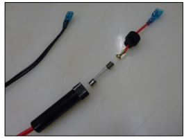
8 . 16 5A Battery Lead Fuse
This section will instruct the correct procedure on how to remove and replace the 5A Battery Lead Fuse.
Removal
1. Remove external covers off the hoist (refer to section 8.1)
2. Disconnect the power lead from PCB.
3. Disconnect the power lead from the batteries. (See section 8.4 for assistance)
4. Unscrew the fuse holder to access and remove the Fuse from the power lead.
Refitting / Replacement
5. Process refitting is a reversal of the removal.
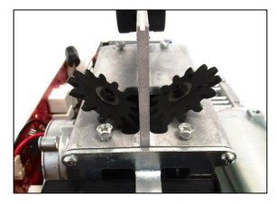
8 . 17 Traverse Idle Gear Within this section it will explain the correct procedure on removing and reinstalling the Traverse Idle Gear for servicing procedures or replacement.
Removal
1. Remove external covers off the hoist (Refer to section 8.1)
2. Remove the wheels from the hoist (Refer to section 8.14)
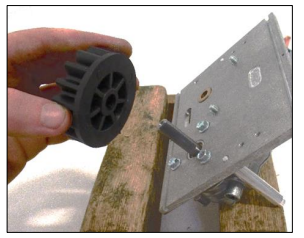
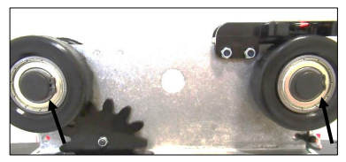
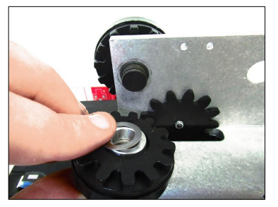
3. Using a 2mm Allen key, Remove the M3x12 screw and M3 nyloc nut to release the traverse idle gear.
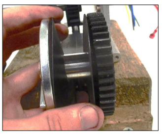
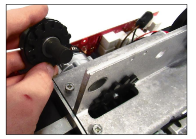
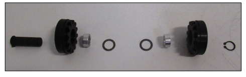
4. Split the male and female parts of the traverse idle gear as shown and remove. Ensure to grab the washers placed between each piece of the traverse idle gears.
Refitting / Replacement
5. Refitting is a reversal of the removal process noting the following point:
• Ensure when fitting the male and female parts together that the shim washers are still in place.
• The Female part of the Traverse Idle Gear must be on the same face as the PCB
• When securing the two gears together, do not overtighten. Once tight, loosen the screw by half a turn to allow the gear ability to rotate freely.
8 . 18 Communications Port
Within this section it will explain the correct procedure on removing and reinstalling the Communications Port for servicing procedures or replacement.
Removal
1. Remove external covers off the hoist. (Refer to section 8.1)
2. Remove the battery from the battery brackets. (Refer to section 8.4)
3. Disconnect the communications port from the PCB.
4. Re-route the wire from behind the PCB and from under the opposite sides’ battery bracket.
5. Cut the three cable ties that secure the wire to the chassis.
6. Using a 2mm Allen key, Remove the M3x12 screws and M3 nyloc nuts to release the charging beak.
Refitting / Replacement
7. Refitting is a reversal of the removal process noting the following point:
Three cable ties are required! – Re-secure the wire with cable ties as instructed below:
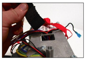
• A1) Insert the cable tie (100mm x 2.5mm) through the top hole in the chassis plate and along the back of the red and black wires.
• Fold the cable tie around the Black wire and pass the cable tie back through the hole and over the red wire.
• Tie the cable tie retaining the black wire and red wire.
• Repeat this process for the second cable tie. For the bottom hole a cable tie 100mm x 2.5mm can be passed through the hole then around the Black and Red wires and tied off. Finally, snip of the surplus cable once secured.
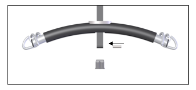
8 . 19 Carry Bar
Within this section it will explain the correct procedure on removing and reinstalling the carry bar for servicing procedures or replacement.
Removal
1. Remove the bung from the base of the carry bar.
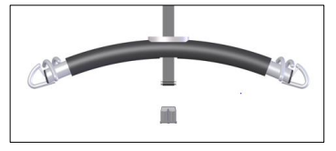
2. Remove the pin from the lift tape loop.
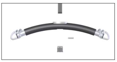
3. Remove the carry bar from the lift tape.
Refitting / Replacement
4. Refitting is a reversal of the removal process noting the following point:
• Ensure to fit the pin back into the carry bar when refitting.