This section will cover the details of how to remove, refit and replace all serviceable parts of the ceiling lift. Ensure to read and understand each step thoroughly before removing any component from the ceiling lift.
Ideally, the ceiling lift should be removed from the track and placed on a work bench before any dismantling. But servicing can be done with the ceiling lift remaining within the track system. (Depending on the service required).
Unless stated otherwise, all images refer to a Mackworth TX600 Advanced with a standard wheel assembly (Track Type 1). Where necessary, additional images for alternative track and ceiling lift types have been included.
Before carrying out any dismantling of the ceiling lift, the power should be turned off using the red pull cord.
8.1 Side Covers
This section will cover the details of how to remove, refit and replace the ceiling lift side covers.
Removal
1. Using an 8mm combination spanner, loosen the four screws from the top face of the ceiling lift. The screws do not need to be removed.
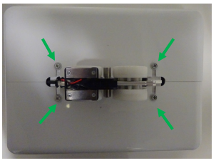
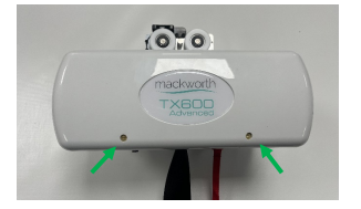
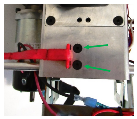
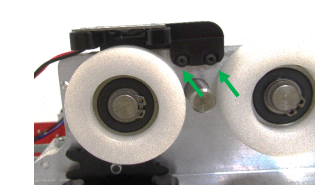
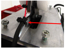
2. Use a slotted screwdriver to remove the two brass screws from the rear cover of the ceiling lift.
3. Gently remove the cover from the ceiling lift
4. Rotate the ceiling lift 180° and gently rest the ceiling lift on the lift motor.
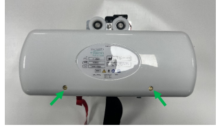
5. Using a slotted screwdriver, remove the two brass screws from the front cover.
6. Gently remove the cover from the Ceiling lift
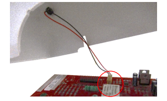
7. (Quick Release Trolley System Ceiling lifts only) – While removing the Cover, ensure to disconnect the charging lead from the PCB.
Refitting / Replacement
Refitting is a reversal of the removal process noting the following points:
• Make sure the profile edges of the covers align with the bottom cover.
• Ensure the slots on the top side of the covers align with four pozi screws.
• Ensure you secure the brass screws first on both covers prior to tightening the four pozi screws.
8.2 Bottom Cover
This section will cover the details of how to remove, refit and replace the ceiling lifts bottom cover.
Removal
1. Remove the side covers from the ceiling lift. (Refer to section 8.1)
2. Remove the QRS Hook from the lift tape. (Refer to section 8.18)
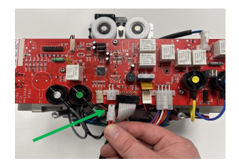
3. Disconnect the power lead from the PCB.
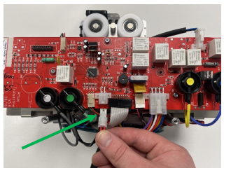
4. Disconnect the LCD and LED cables from the PCB.
5. Gently move the bottom cover away from the chassis and feed the cover through the lift tape.
Refitting / Replacement
Refitting is a reversal of the removal process noting the following points:
• Make sure cover slot is fed through the lift tape in the correct direction, so the red cord and grommet align with their slots.
• Ensure the red pull cord is pulled through its designated slot.
• Ensure that the grommet is pushed through its designated slot.
• Ensure that the bottom cover is flush up against the bottom of the chassis.
8.3 Batteries
This section will cover the details of how to remove, refit and replace the batteries.
Removal
1. Remove the side covers from the ceiling lift. (Refer to section 8.1)
2. Disconnect the power lead from the PCB.
3. Disconnect the battery leads from their terminals. (this can be done without undoing the top Velcro straps.
3. Disconnect the battery leads from their terminals. (this can be done without undoing the top Velcro straps.
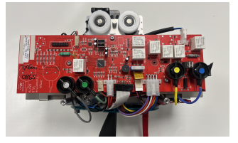
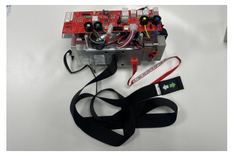
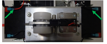
4. Release the side Velcro straps to give access to the batteries.
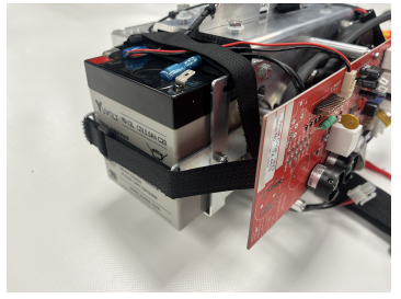
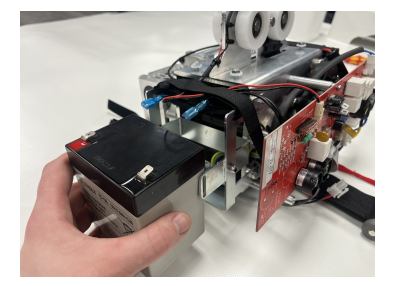
5. Slide the batteries out from their battery brackets to remove.
Refitting / Replacement
Refitting is a reversal of the removal process noting the following points:
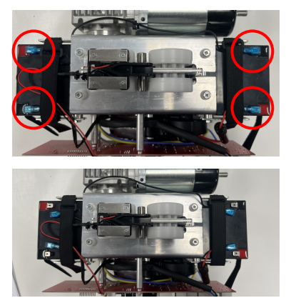
• Ensure to place the batteries back into the brackets in the correct orientation. (the terminals should be pointing inwards).
• Ensure the main power lead is re-attached with the red lead connecting to the red terminal on the battery and the black lead connecting to the black terminal on the battery.
• The link lead can be attached in either direction.
• Ensure the Velcro is reattached correctly
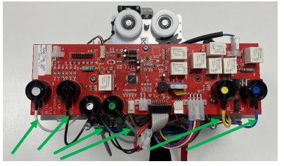
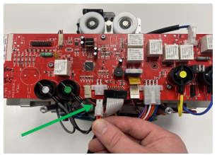
8.4 PCB
This section will cover the details of how to remove, refit and replace the PCB. Images below refer to a 6-way board, the process is the same for each of the other PCB options, but with less connections.
Removal
1. Remove the side covers from the ceiling lift. (Refer to section 8.1)
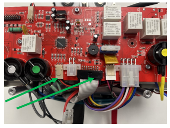
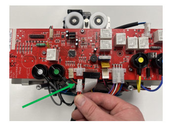
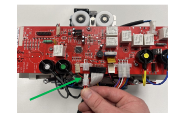
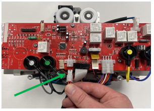
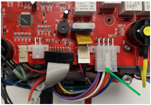
2. Disconnect the power lead from the PCB.
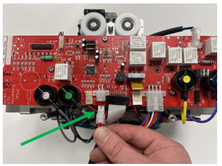
3. Remove the remaining connections from the PCB ports. There is no correct order to disconnect.
• Toggle Switch
• Limit Switch
• LCD
• LED
• Charging Beak
• Air Tubes (2 to 6)
• Traverse Motor (if applicable)
• Auxiliary beak (if applicable)
4. Using a 2.5mm Allen Key, remove the three M3 screws securing the board to the chassis.
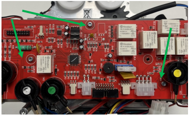
5. The PCB can now be removed from the ceiling lift.
Refitting / Replacement
Refitting is a reversal of the removal process noting the following points:
• The power lead should always be connected last.
• Make sure to connect each component to the correct port.
• Ensure that the air tubes are fully situated onto the brass inserts on the air switches.
• The air switches are colour coded with a sticker to guide on connecting the correct air tube to the correct air switch.
• Be careful not to split the air tubes during refitment.
• Make sure to secure the PCB to the chassis before reconnecting the power, do not allow the board to
come into contact with the chassis other than its designated mounts.
8.5 Lift Motor
This section will cover the details of how to remove, refit and replace the Lift Motor.
Removal
1. Remove the side covers from the ceiling lift. (Refer to section 8.1)
2. Disconnect the power lead from the PCB.
3. Remove the motor side battery, (recommended for easier refitment but not necessary). Refer to section 8.3.
4. On the underside of the motor side battery bracket, disconnect the motor lead terminals.
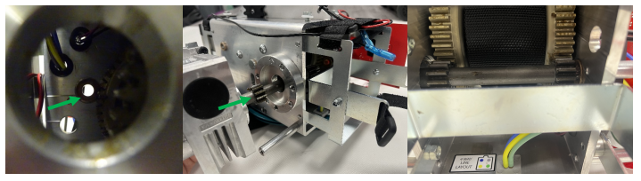
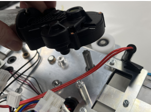
5. Using a 5mm Allen Key, remove the three bolts securing the motor to the chassis.
6. Remove the motor from the chassis, be careful not to damage the gear shaft during removal.
Refitting / Replacement
Refitting is a reversal of the removal process noting the following points:
• Ensure that the motor aligns with the tapped holes on the motor mount.
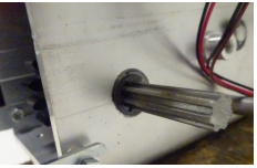
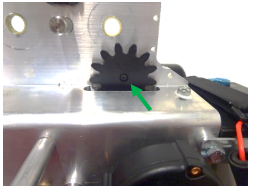
• Ensure that the motor gear shaft aligns and fits into the oilite bush found on the other face of the chassis.
• The motor shaft gearing should mesh with the hub teeth
• Ensure that the motor cables are with the correct terminals. Red to red, black to black.
8.6 Lift Tape
This section will cover the details of how to remove, refit and replace the Lift Tape.
Removal
1. Remove the side covers from the ceiling lift. (Refer to section 8.1)
2. Disconnect the power lead from the PCB.
3. Remove the QRS hook from the ceiling lift. (Refer to section 8.18)
4. Remove the bottom cover from the ceiling lift. (Refer to section 8.2)
5. Remove the motor side battery from the ceiling lift. (Refer to section 8.3)
6. Remove the lift motor from the ceiling lift. (Refer to section 8.5)
7. PCB removal is recommended for easier access. (Refer to section 8.4)
8. Pull the lift tape from the ceiling lift until it has fully unwound from the hub.
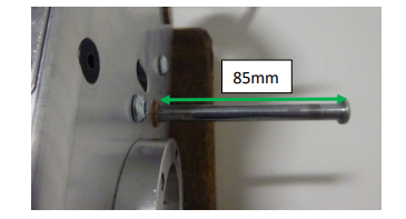
9. Using a small slotted screwdriver, remove the 8mm e-clip from the strap pin. Be careful not to lose the e-clip.
10. Slide the strap pin out of the chassis until 85mm of the pin is visible, this allows lift tape removal without displacing the hub.
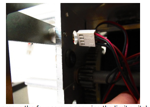
11. Gently pull the lift tape through the limit switch block to remove it from the ceiling lift.
Refitting / Replacement
Refitting is a reversal of the removal process noting the following points:
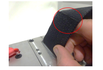
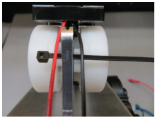
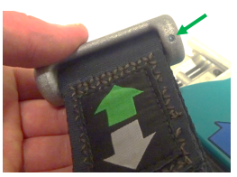
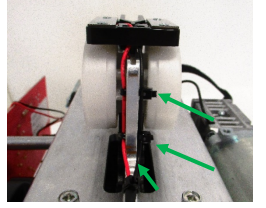
• When refitting the lift tape, ensure that the stitching fold is facing the red pull cord. (See image above)
• For easier refitment, open up the loop of the tape as shown, this can make it easier for the strap pin to fit through the tape when inside the hub.
• When sliding the pin back through the chassis, be careful not to catch the lift tape and cause damage to its integrity.
• Inspect the condition of the e-clip, if the clip has been stretched, replace with a new e-clip.
• Once the pin is pushed back through the chassis, ensure to refit the e-clip. This is done using long nose pliers, be careful not to damage the PCB if it hasn’t been removed.
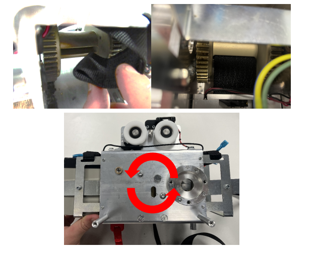
• Wind the lift tape around the hub by rotating the hub in an anti-clockwise direction.
• Pull the lift tape while holding the hub to allow the lift tape to stretch and tighten, then continue to wind
around the hub.
• Refit the removed components to the ceiling lift.
8.7 Hub
This section will cover the details of how to remove, refit and replace the Lift Tape.
Removal
1. Remove the side covers from the ceiling lift. (Refer to section 8.1)
2. Disconnect the power lead from the PCB.
3. Remove the bottom cover from the ceiling lift. (Refer to section 8.2)
4. Remove the motor side battery from the ceiling lift. (Refer to section 8.3)
5. Remove the lift motor from the ceiling lift. (Refer to section 8.5)
6. PCB removal is recommended for easier access. (Refer to section 8.4)
7. Remove the lift tape from the ceiling lift (Refer to section 8.6)
8. Remove the air grommet assembly from the ceiling lift. (Refer to section 8.10)
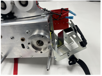
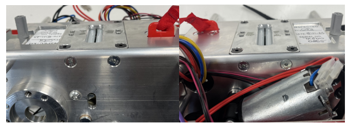
9. Using an 8mm combination spanner, loosen the M5 x 12 screw (with the spacer behind) from the top end of the battery bracket on the motor side.

10. Using an 8mm combination spanner, remove the M5 x 12 screw (screw head is on inside of chassis) from the opposite side of the top end of the battery bracket on the motor side.
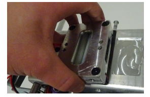
11. Pivot the battery bracket to allow access to the inside of the chassis.
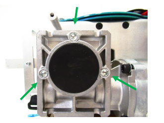
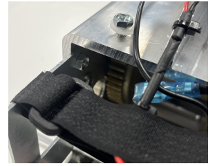
12. Using a 4mm Allen Key, remove the three M6 x 16 screws from the front face of the chassis (these are the over speed cam screws)
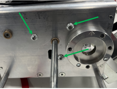
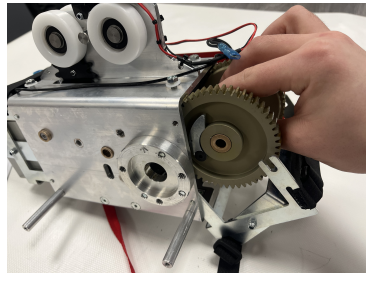
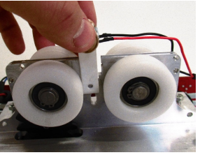
13. Fully remove the strap pin from the chassis, while supporting the hub with your other hand to avoid any damage.
14. Guide the hub out of the chassis past the pivoted battery bracket
Refitting / Replacement
Refitting is a reversal of the removal process noting the following points:
• When refitting the hub, if required, grease the hub using the recommended grease (Morris Grease – K42EP multi-purpose).
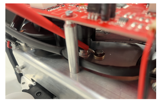
• When inserting the hub back into the chassis, make sure the overspeed cam is facing the rear face of the chassis (Lift Motor side).
• Make sure to refit the overspeed cam screws into the chassis.
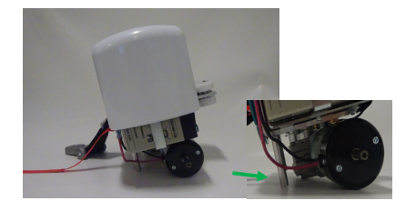
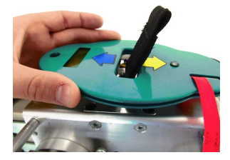
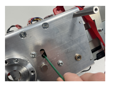
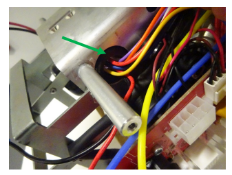
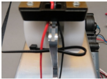
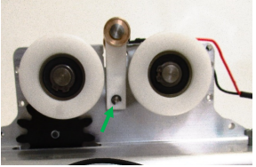
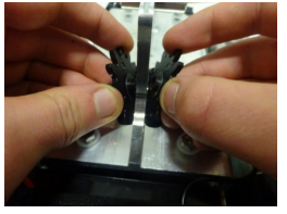
• Test the overspeed cam is working by flicking the cam with an Allen Key through the slot in the chassis. (See image below)
• Refer to the lift tape refitting guide for further details.
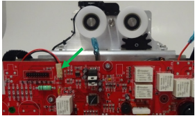
8.8 Limit Switch Block
This section will cover the details of how to remove, refit and replace the Limit Switch Block.
Removal
1. Remove the side covers from the ceiling lift. (Refer to section 8.1)
2. Disconnect the power lead from the PCB.
3. Remove the bottom cover from the ceiling lift. (Refer to section 8.2)
4. Remove the motor side battery from the ceiling lift. (Refer to section 8.3)
5. Remove the lift motor from the ceiling lift. (Refer to section 8.5)
6. PCB removal is recommended for easier access. (Refer to section 8.4)
7. Remove the lift tape from the ceiling lift (Refer to section 8.6)
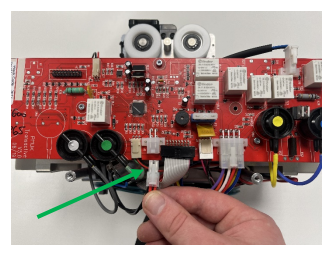
8. If the PCB hasn’t been removed, disconnect the limit switch cable from its allocated port on the PCB.
9. Using a slotted screw driver, prise the limit switch cable grommet from the chassis.
10. Guide the limit switch cable through the chassis.
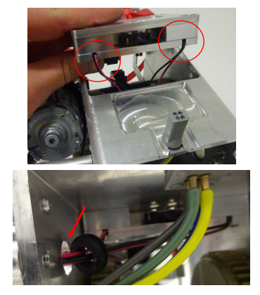
11. Using a 3mm Allen Key, remove the four screws securing the limit switch block on either face of the chassis.
12. Once the four screws have been removed, remove the limit switch block from the underside of the chassis. Be careful not to trap/catch the wiring while removing.
Refitting / Replacement
Refitting is a reversal of the removal process noting the following points:
• Ensure that the wiring is inserted through the chassis opening first.
• Be careful not to trap the wiring during fitting.
• Ensure that the limit switch block is fitted in the correct orientation. The wiring should be facing the motor side of the ceiling lift (wires will face the same direction as the air grommet).
• Once the limit switch block is secured, pull the wiring through the grommet hole and ensure the wiring slackness is on the outside of the chassis. Do not allow slack cable on the inside of the chassis as this could risk contact with the gearing.
• Ensure that the grommet is secure in the chassis.
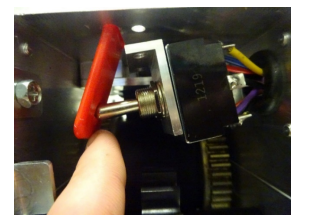
8.9 Toggle Switch and E-Lower Cord
This section will cover the details of how to remove, refit and replace the Toggle Switch.
Removal
1. Remove the side covers from the ceiling lift. (Refer to section 8.1)
2. Disconnect the power lead from the PCB.
3. Remove the bottom cover from the ceiling lift. (Refer to section 8.2)
4. Remove the toggle switch side battery from the ceiling lift. (Refer to section 8.3)
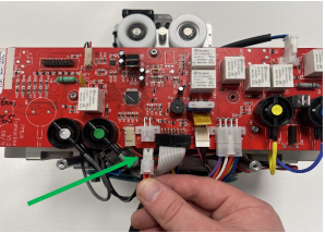
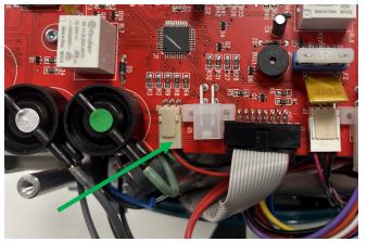
5. Disconnect the toggle switch from the PCB.
6. Disconnect the motor wires from the toggle switch terminals.
7. The cable tie may need cutting to release the toggle switch cables.
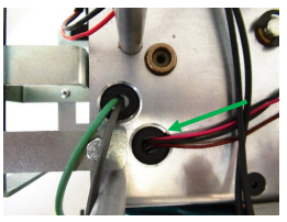
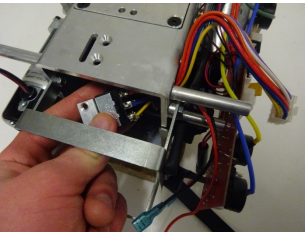
8. Using a slotted screwdriver, detach the large grommet by pushing it through the chassis
9. Using a 3mm Allen Key, remove the two M5 countersink screws from the underside of the chassis.
10. Unhook the e-lower cord from the toggle switch inside the chassis.
11. Pull the red cord through the chassis slit to remove.
12. Pull the toggle switch block through the side opening of the chassis, be careful not to damage the wiring during removal.
Refitting / Replacement
Refitting is a reversal of the removal process noting the following points:
• Be careful not to trap the wiring during fitting.
• Once the toggle switch block is secured, pull the wiring through the grommet hole and ensure the wiring slackness is on the outside of the chassis. Do not allow slack cable on the inside of the chassis as this could risk contact with the gearing.
• Ensure that the grommet is secure in the chassis.
• A cable tie is required to secure the motor cables to the underside of the battery bracket.
• The red cord warning label should be facing the lift motor.
• The red cord will sit on the switch before securing the M5 countersink screws.
8.10 Air Grommet
This section will cover the details of how to remove, refit and replace the Air Grommet.
Removal
1. Remove the side covers from the ceiling lift. (Refer to section 8.1)
2. Disconnect the power lead from the PCB.

3. Remove the bottom cover from the ceiling lift. (Refer to section 8.2)
4. Remove the motor side battery from the ceiling lift. (Refer to section 8.3)
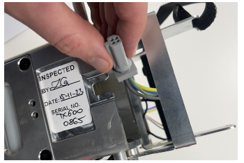
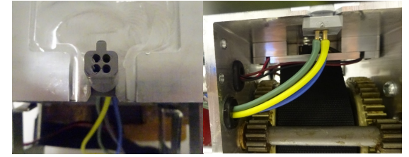
5. Disconnect the air tubes from their designated air switches on the board. The tubes are colour coded to match the stickers found on the air switches.
6. Pull the air tubes through the grommet on the side face of the chassis.
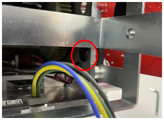
7. Slide the air grommet out of the chassis as shown.
Refitting / Replacement
Refitting is a reversal of the removal process noting the following points:
• Fit the air grommet back into position and ensure to aligned in the correct orientation.
• Be careful not to trap the air tubes during fitting.
• Once the air grommet is secured, pull the air tubes through the grommet hole and ensure the tube slackness is on the outside of the chassis. Do not allow slack tubes on the inside of the chassis as this could risk contact with the gearing.
• Insert the coloured air tubes back onto their colour-matching air switches. Make sure to fit the air tube fully onto the brass inserts for a secure connection.
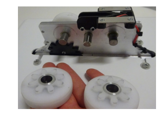
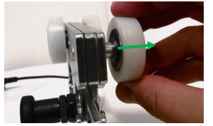
8.11 Standard Wheels
This section will cover the details of how to remove, refit and replace the standard wheels, this section covers all wheel variants excluding the QRT wheel assembly. The images below refer to track type 1 wheels but the same procedure will apply to all other track types.
Removal
1. Using circlip pliers, remove the circlips from the wheel axel on both wheels.
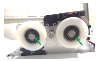
2. Remove the wheels and spacers from the circlip side of the chassis trolley.
3. Remove the axels with the remaining wheels and spacers from the opposite side of the chassis.
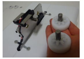
4. There may be shim washers found spacing out the wheels on either side. Ensure to note their location for refitment.
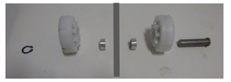
Refitting / Replacement
Refitting is a reversal of the removal process noting the following points:
• When refitting the wheels, see the exploded diagram below for guidance on the assembly order.
• Inspect the condition of the e-clips, if the clips have been stretched, replace with a new e-clip.
8.12 QRT System Wheels
This section will cover the details of how to remove, refit and replace the QRT system wheels. The images below refer to track type 1 wheels but the same procedure will apply to all other track types.
Removal
1. Using two 4mm Allen Keys, remove the screw, the wheels and the seven washers from the axels securing the wheel assemblies.
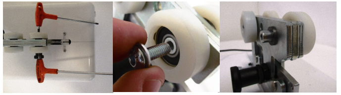
2. Remove the axels with the remaining wheels and washers from the opposite side of the chassis.
Refitting / Replacement
Refitting is a reversal of the removal process noting the following points:
• Make sure to fit the seven washers on either side of the trolley during refitment.
8.13 Standard Charging Beak
This section will cover the details of how to remove, refit and replace the standard charging beak.
Removal
1. Remove the side covers from the ceiling lift. (Refer to section 8.1)
2. Disconnect the power lead from the PCB.
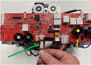
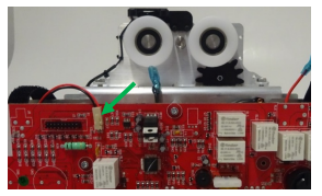
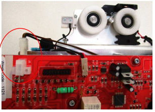
3. Disconnect the charging beak cable from the PCB port.
4. Release the top Velcro strap from the motor side battery.
5. Cut the three cable ties which route the beaks cable up to the top of the trolley.
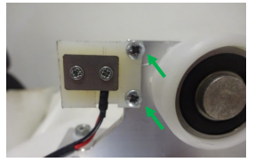
6. Using a 2mm Allen Key, remove the two M3 screws which secure the charging beak to the trolley top. It is easier to remove the screws by using long nose pliers to pinch the M3 nyloc nuts on the rear side.
Refitting / Replacement
Refitting is a reversal of the removal process noting the following points:
• Three cable ties are required to re-route the cable along the side face of the chassis trolley.
• Ensure to route the beak cable under the top Velcro strap on the battery bracket.
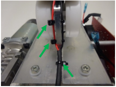
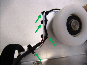
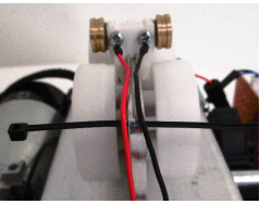
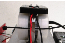
Cable tie instructions
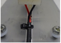
1. Insert the first cable tie through the top hole in the chassis and along the back of the red and black wires.
2. Fold the cable tie around the Black wire and pass the cable tie back through the hole and over the Red wire.
3. Tie the cable tie to retain the black and red wire.
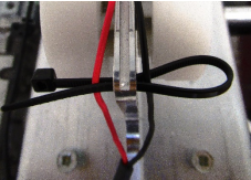
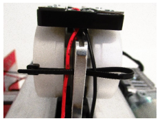
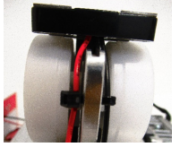
4. Repeat step 1-3 for the second cable tie.
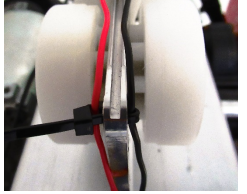
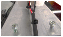
5. For the final cable tie, (bottom hole), pass the cable tie through the hole and then back around across the red and black wires and chassis face.
6. Cut the surplus of the three cable ties once secure.
8.14 Charging Beak ( Varient Beak type)
This section will cover the details of how to remove, refit and replace the variant charging beak.
Removal
1. Remove the side covers from the ceiling lift. (Refer to section 8.1)
2. Disconnect the power lead from the PCB.
3. Disconnect the charging beak cable from the PCB port.
4. Release the top Velcro strap from the motor side battery.
5. Cut the single cable tie which route the beaks cable up to the top of the trolley.
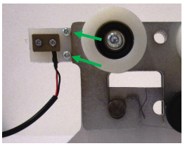
6. Using a pozi-screwdriver, remove the two screws securing the beak to the trolley
Refitting / Replacement
Refitting is a reversal of the removal process noting the following points:
• One cable tie is required to re-route the cable along the side face of the chassis trolley.
• Ensure to route the beak cable under the top Velcro strap on the battery bracket.
Cable tie instructions
1. Pass the cable tie through the hole and then back around across the red and black wires and chassis face.
2. Cut the surplus of the cable tie once secure.
8.15 QRT System Charging Beak
This section will cover the details of how to remove, refit and replace the QRT system charging beak.
Removal
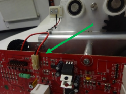
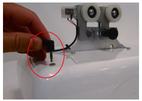
1. Disconnect the beak jack plug from the top side of the side cover port.
2. Cut the cable tie securing the wire to the chassis trolley.
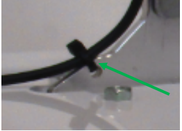
3. Using a pozi-screwdriver, remove the two screws securing the beak to the trolley.
Refitting / Replacement
Refitting is a reversal of the removal process noting the following points:
• One cable tie is required to re-route the cable along the side face of the chassis trolley.
Cable tie instructions
1. Pass the cable tie through the hole and then back around across the red and black wires and chassis face.
2. Cut the surplus of the cable tie once secure.
8.16 Constant Charge Beak
This section will cover the details of how to remove, refit and replace the constant charge beak.
Removal
1. Remove the side covers from the ceiling lift. (Refer to section 8.1)
2. Disconnect the power lead from the PCB.

3. Disconnect the charging beak cable from the PCB port.
4. Release the top Velcro strap from the motor side battery.
5. Cut the four cable ties which route the beaks cable up to the top of the trolley
6. Using a 2mm slotted screwdriver, remove the e-clip securing the charging beak pin.
7. Remove the pin to release the charging beak. Ensure not to lose the spring situated inside the beak.
Refitting / Replacement
Refitting is a reversal of the removal process noting the following points:
• When sliding the constant charge beak into position, ensure to fit the spring into the hole at the top of the chassis trolley before placing the beak on top. The spring allows the beak to move vertically and touch onto the charging strips.
• Three cable ties are required to re-route the cable along the side face of the chassis trolley.
• Ensure to route the beak cable under the top Velcro strap on the battery bracket.
Cable tie instructions
1. Insert the first cable tie through the top hole in the chassis and along the back of the red and black wires
2. Fold the cable tie around the Black wire and pass the cable tie back through the hole and over the Red wire.
3. Tie the cable tie to retain the black and red wire.
4. Repeat step 1-3 for the second and third cable tie.
5. For the final cable tie, (bottom hole), pass the cable tie through the hole and then back around across the red and black wires and chassis face.
6. Cut the surplus of the four cable ties once secure.
8.17 Battery Fuse
This section will cover the details of how to remove, refit and replace the battery fuse.
Removal
1. Remove the side covers from the ceiling lift. (Refer to section 8.1)
2. Disconnect the power lead from the PCB.

3. Release the top Velcro strap from both batteries to access the battery cables.
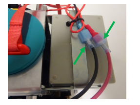
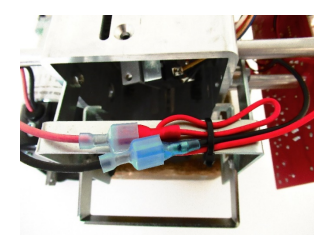
4. Disconnect the power lead from the batteries to remove.
5. Unscrew the fuse holder on the power lead to access the fuse.
Refitting / Replacement
Refitting is a reversal of the removal process noting the following points:
• Ensure to connect the red lead back to the red battery terminal and the black lead to the black battery terminal.
8.18 QRS Hook
This section will cover the details of how to remove, refit and replace the QRS Hook.
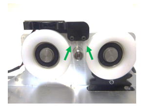
Removal
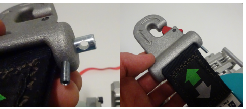
1. Using a 2mm Allen Key, loosen the grub screw from the hook until it releases the pin. The grub screw doesn’t need to be fully removed.
2. Slide the pin out from the lift tape to release the QRS Hook.
Refitting / Replacement
Refitting is a reversal of the removal process noting the following points:
• Ensure that the hole in the pin aligns with the grub screw.
• Ensure that the red tab on the QRS Hook is facing the motor face of the chassis.
• Care must be taken not to damage the lift tape when inserting the pin through the loop.
8.19 Drive Motor
This section will cover the details of how to remove, refit and replace the Drive Motor. (Only applicable to powered traverse ceiling lifts)
Removal
1. Remove the side covers from the ceiling lift. (Refer to section 8.1)
2. Remove the PCB from the ceiling lift. (Refer to section 8.4)
3. Using a 5mm Allen Key, remove the two M6 Bolts which secure the drive motor to the chassis.
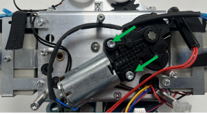
4. Slide the motor of the drive shaft.
Refitting / Replacement
Refitting is a reversal of the removal process noting the following points:
• Ensure to align the drive motor in the correct orientation for mounting.
8.20 Drive Shaft Assembly
This section will cover the details of how to remove, refit and replace the Drive Shaft Assembly. (Only applicable to powered traverse ceiling lifts)
Removal
1. Remove the side covers from the ceiling lift. (Refer to section 8.1)
2. Remove the PCB from the ceiling lift. (Refer to section 8.4)
3. Remove the drive motor from the ceiling lift. (Refer to section 8.19)
4. Remove the toggle switch side battery from the ceiling lift. (Refer to section 8.3)
5. Using a slotted screwdriver, remove the 8mm e-clip from the traverse shaft.
6. Remove the washer situated behind the e-clip.
7. While supporting the two black spacers and the large idle gear, slide the drive shaft out of the chassis. (It’s good to note which spacer is which as they are different lengths and must be refitted correctly).
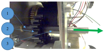
8. Remove the two black spacers and large idle gear from the chassis.
Refitting / Replacement
Refitting is a reversal of the removal process noting the following points:
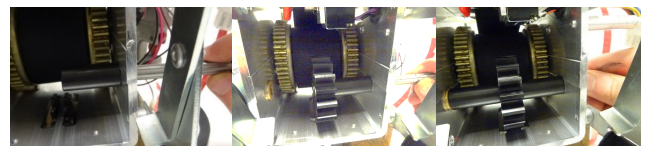
• Begin to insert the drive shaft, with the longest spacer (37.1mm) placed on the shaft first, then the large idle gear then the shortest spacer (34.3mm).
• Push the shaft into the bush at the opposite end of the chassis. Ensure the shaft is flush with the bush.
• Make sure to position the washer and secure the e-clip to the shaft once inserted.
8.21 Small Drive Idle Gear
This section will cover the details of how to remove, refit and replace the Small Drive Idle Gear. (Only applicable to powered traverse ceiling lifts)
Removal
1. Remove the side covers from the ceiling lift. (Refer to section 8.1)
2. Remove the wheel directly above the idle gear. (Refer to section 8.11)
3. Using a 2mm Allen Key, remove the M3 screw and M3 nyloc nut to release the idle gear. We recommend using long nose pliers to grip the nyloc nut.
4. Split the male and female parts of the idle gear and remove. Ensure to grab the washers placed behind the mating parts.
Refitting / Replacement
Refitting is a reversal of the removal process noting the following points:
• Ensure to position the shim washers behind the mating parts when joining the idle gear.
• Position the female mating part on the same chassis face as the PCB.
• When securing the two parts together with the screw, do not overtighten. Once tight, loosen the screw by a half turn to allow the gear to rotate freely.
8.22 Auxiliary Beak
This section will cover the details of how to remove, refit and replace the auxiliary beak. (Only applicable to auxiliary ceiling lifts – 6-way ceiling lift)
Removal
1. Remove the side covers from the ceiling lift. (Refer to section 8.1)
2. Disconnect the power lead from the PCB.

3. Disconnect the auxiliary beak cable from the PCB port.
4. Release the top Velcro strap from the toggle switch side battery.
5. Cut the three cable ties which route the beaks cable up to the top of the trolley
6. Using a 2mm Allen Key, remove the two M3 screws which secure the charging beak to the trolley top. It is easier to remove the screws by using long nose pliers to pinch the M3 nyloc nuts on the rear side.
Refitting / Replacement
Refitting is a reversal of the removal process noting the following points:
• Three cable ties are required to re-route the cable along the side face of the chassis trolley.
• Ensure to route the beak cable under the top Velcro strap on the battery bracket, then route the cable behind the PCB up until the auxiliary port on the opposite side.
Cable tie instructions
1. Insert the first cable tie through the top hole in the chassis and along the back of the red and black wires
2. Fold the cable tie around the Black wire and pass the cable tie back through the hole and over the Red wire.
3. Tie the cable tie to retain the black and red wire.
4. Repeat step 1-3 for the second cable tie.
5. For the final cable tie, (bottom hole), pass the cable tie through the hole and then back around across the red and black wires and chassis face.
6. Cut the surplus of the three cable ties once secure.